| Features |
Hyson Cells with concrete
Load transfer
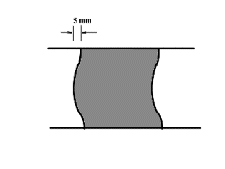
The Hyson Cells joint exhibits a 3D lockup mechanism. This lockup provides shear transfer for wheel loads moving across joints and load transfer to prevent differential faulting of adjacent cast blocks.
The interlock somewhat resembles a rounded keyway joint and somewhat an elbow joint.
Joint gap
When the Hyson Cells formwork is initially filled with concrete there is no gap between the wet infill and the plastic cell wall. During curing the concrete shrinks and gaps will form at the edges of the cast blocks. Even using a highly workable concrete with slumps of 150 mm a maximum curing shrinkage of less than 800 microstrain will be expected. With a cast block of side 150 mm (the most common Hyson Cells size for load support applications) this translates to a maximum gap of only 0.12 millimetres.
Non-plane face
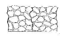
The face of the cast Hyson Cells block is not a flat plane face but is slightly distorted. The distortions create protrusions nested in cavities when the cell is filled.
If high slump ready-mix concrete is used then the rigging is used to slightly wrinkle or buckle the cell wall before the fill is placed.
 The cells buckle slightly
The discussion on joint gap above shows that the gap after curing is unlikely to exceed 0.03 mm on either side of the plastic. The non-planar distortion required for an interlocking effect to be exhibited is therefore only a few millimetres. There is no need to deform the walls to the extent that they interfere with the design thickness.
If grouted concrete is used as fill then the coarse aggregate is placed in the cells dry and compacted. The aggregate distorts the cell walls. Cement grout is then poured to fill the voids and lock the aggregate in position. (However good site supervision is needed to ensure that adequate penetration of the grout is achieved.
 Grouted concrete distorts the wall
3D interlock
Deflections take place when the soil beneath the loaded block subsides or compresses. Rotations are required to distribute point loads. After only a small rotation the minute gap at the joint closes, arching then commences and the pavement begins to "lock up". From then on load distribution takes place.
The interlock therefore gives :
- Load distribution
- Pavement flexibility
- Shear strength
Measured performance
Detailed trials were conducted at a container yard in 1998. A 55m x 6m road section comprising 11 panels of a variety of layerwork, overlain by a running surface of either Hyson-Cells or conventional industrial paving, was tested under superloaded conditions using a Kalmar 4160 RS4 Reach-stacker with a maximum front axle payload of 100 tons. (The purpose of these trials was to obtain design input information and not to install a pavement that would last. Hence the range of pavements from weak to strong). The pavement behaviour was independently monitored by the Spoornet Track Testing Centre's mobile strain laboratory using a series of pressure transducers, strain beams and multi-depth deflectometers (MDDs) mounted strategically within the layerwork. Conclusions were that due to the 3D mechanical interlock :
- Less deflection
- Less layerwork needed
- Hyson-Cell blocks don't punch through even with fully saturated layerwork.
- Hyson-Cells paving survives rigorous slew tests.
- Container yards
- Mine roads
- Hard standing areas
- Causeways
- Airport runways
- Industrial paving
- Overlay layer for repairs to existing paving
- Bus routes
|
Contact us at info@hysoncells.co.za |